
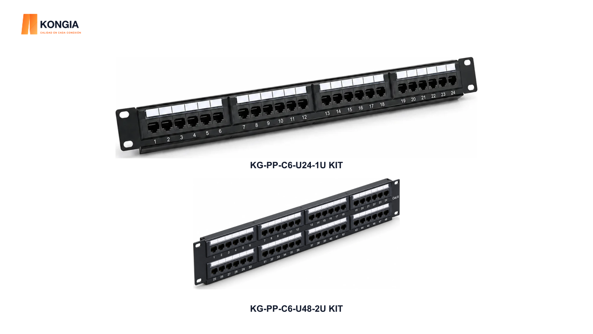
Quick answer. Count terminated outlets, reserve the required rack units and inspect rear access before choosing a panel. The KONGIA 24-port UTP kit occupies 1U; the 48-port UTP kit occupies 2U. Both are loaded IDC 110 panels, not feed-through RJ45 coupler panels. Shielding is a separate design choice.
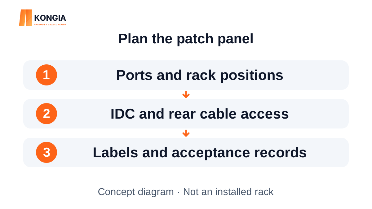
1. Turn the outlet schedule into a port map
List each wall outlet or equipment location with a unique cable identifier. Separate the ports needed now from planned additions, and decide where each identifier will appear on the front panel and at the far end. A 48-port panel is not automatically the better choice for a smaller installation.
Compare a single 48-port unit with two 24-port units against the actual cabinet layout. Do not assume they have interchangeable accessories or maintenance clearances. Record the reserved rack positions and the route used to reach each block.
2. Compare the actual loaded kits
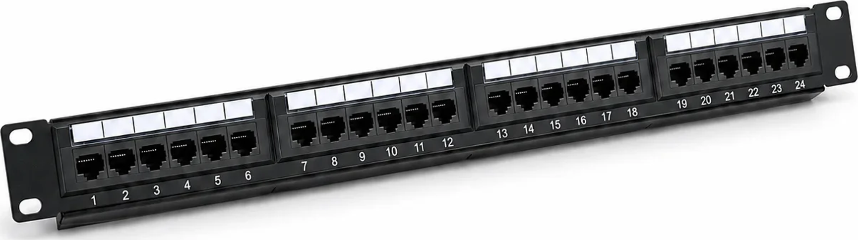
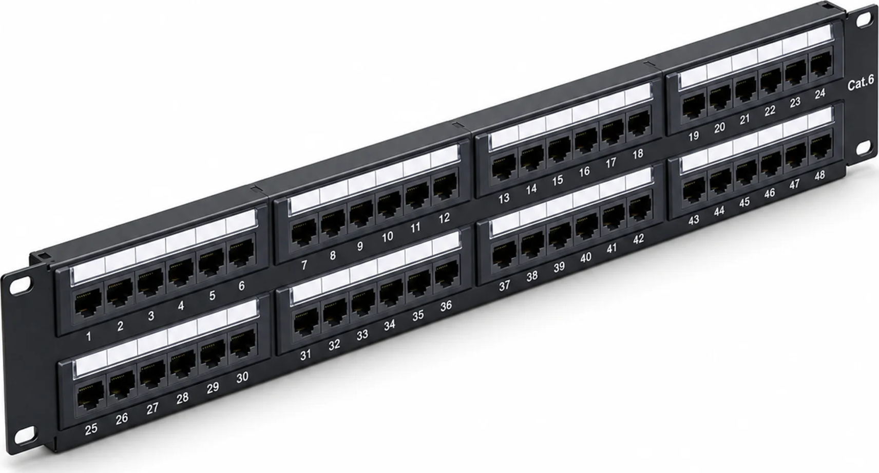
KG-PP-C6-U24-1U KIT lists 24 ports in one row, 1U height, a 19-inch rack format and four removable six-port blocks. KG-PP-C6-U48-2U KIT lists 48 ports in two rows, 2U height and eight six-port blocks. All blocks are included in each complete kit.
These are UTP panels with IDC 110 conductor termination. They are not RJ45 female-to-female feed-through panels. A removable multiport block is not a claim that every individual jack can be removed.
| Check | 24-port UTP kit | 48-port UTP kit |
|---|---|---|
| Exact reference | KG-PP-C6-U24-1U KIT | KG-PP-C6-U48-2U KIT |
| Rack space | 1U; 19-inch rack format | 2U; 19-inch rack format |
| Port layout | One row of 24 | Two rows of 24 |
| Loaded modules | Four blocks of six | Eight blocks of six |
| Rear management | One support with self-locking rings | Two supports with self-locking rings |
| Termination / unit | IDC 110; one complete kit | IDC 110; one complete kit |
3. Check the rear space, not just the front height
For the 24-port UTP reference, the published panel dimensions without its rear support are 483 × 45 × 35 mm. That is not the depth required by the full cable assembly. Allow for the actual support, cable approach, bend requirements, rack rails and equipment already installed.
Open the planned cabinet or review a dimensioned layout. Check whether a technician can reach both the IDC blocks and cable supports without stressing other connections. Ask for the missing installed-clearance information instead of transferring the 24-port body dimension to the 48-port model.
4. Keep shielding and termination choices separate
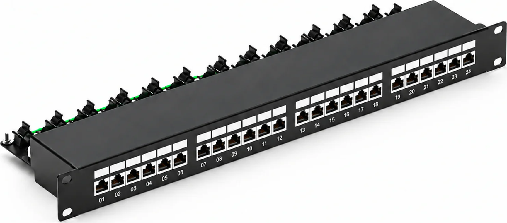
KG-PP-C6-S24-1U KIT is the shielded 24-port, 1U alternative in this comparison. Its specification lists loaded removable multiport blocks, IDC 110, rear cable support and a grounding connection and lead. The included grounding accessory does not complete the project bonding design.
Confirm the chosen cabling system, cable suitability and termination requirements before ordering. The shielded 24-port reference explicitly lists 22–26 AWG; do not transfer that range to the UTP models without a matching specification. Follow the product marking and the agreed T568A or T568B scheme consistently.
5. Record acceptance at the cable, not only the panel
Give each completed link a record connecting cabinet, panel and port to its far-end outlet. Fluke explains that wire-map verification checks conductor connections but does not establish bandwidth performance. Agree the actual acceptance method and limits for the project separately.
The listed kits include an IDC 110 insertion tool. Tool inclusion is not evidence that a termination has passed inspection. Keep the component references, selected scheme, identified links and test reports with the handover information.
6. Send a cabinet-specific quotation brief
Provide the outlet count, current and reserved rack positions, cabinet drawing, cable type, shielding design and destination. Ask for confirmation of any unresolved cable-gauge, rear-clearance or mounting detail before approving the order.
- Map cable identifiers to panel ports and far-end outlets.
- Reserve 1U or 2U based on the exact reference.
- Confirm IDC termination rather than feed-through coupling.
- Check rear cable support, access and bonding requirements.
- Agree link records, acceptance reports and kit quantities.
Related KONGIA products
Questions before ordering
Does loaded mean I must buy the jacks separately?
No. These selected KONGIA kits list all module blocks as included. Confirm the exact kit reference and accessories in the quotation.
Can I plug a finished RJ45 cable into the rear?
These references use IDC 110 conductor termination. They are not feed-through RJ45 coupler panels.
Does a 35 mm panel body mean a 35 mm installed depth?
No. The 24-port UTP body dimension excludes the rear support. Cabling, bends, access and cabinet hardware require a separate clearance check.
Does a successful wire map certify Cat6 performance?
No. Wire map is a connection check. Use the agreed project acceptance method and relevant performance reports.
The KONGIA approach
KONGIA aims to make rack connectivity easier to select, explain and maintain. Clear kit contents, honest clearance checks and traceable port records help partners discuss an installation with confidence. We seek to simplify sourcing and use while respecting distributor investment and the responsibilities agreed in writing.
Our purpose and values →Sources and scope
Installation-planning guidance based on the exact product references, not a rack-engineering design or certified test result. Check the project drawings, cable instructions and acceptance requirements. No dimensions or cable ranges are transferred to unverified models.
- KONGIA — KG-PP-C6-U24-1U KIT
- KONGIA — KG-PP-C6-U48-2U KIT
- KONGIA — KG-PP-C6-S24-1U KIT
- Fluke Networks — Wire-map testing and its scope
Prepared with AI assistance and the listed references. The diagrams are conceptual; they do not show a customer installation or a completed performance test. The product images use approved KONGIA catalog originals; separate technical diagrams remain explanatory. Editorial policy